Pump and Turbine Characteristics in WaterGEMS
The pump and turbine characteristics used in WaterGEMS are defined in the following files:
- C:\Program Files\Bentley\<Product Name>10\QuadrantCurvesPredefined.txt
- C:\Program Files\Bentley\<Product Name>10\QuadrantCurves.txt
The 'QuadrantCurvesPredefined.txt' file contains predefined pump and turbine characteristics, and should not be edited.
The 'QuadrantCurves.txt' file is available for users to enter their own data.
Both files contain characteristics for pump/turbine units of a particular specific speed. When defining a pump or turbine in the WaterGEMS application itself, users should select the closest available specific speed to the unit they are modeling.
If the actual pump or turbine characteristics are available, users should enter those using them methods described in this document.
General
The files start with the following header:
*** <Product Name> AUXILIARY DATA FILE ***
Each file is then broken into two sections - one for pumps and one for turbines - as indicated by the following lines in the file:
[PUMPS]
[TURBINES]
Pump Data
Pump data can be specified in one of the following formats: , circular format, Suter format, Suter Thorley format, or Suter Chaudhry format. Details for the different formats are as follows.
Circular
The relative values of Q (flow) and N (speed) along lines of 100% head (QH and NH) and 100% torque (QM and NM) are entered at a suitable interval throughout the entire operating range of the pump. WaterGEMS can then use these curves to calculate the values of head and torque for any values of Q and N using homologous relations.
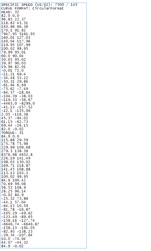
The data file format is given below - fields in italics need to be replaced with appropriate values: SPECIFIC SPEED (US/SI): [Specific speed, US units] / [Specific speed, SI units]CURVE FORMAT: CircularFormatHEAD: NHDQH,1 NH,1QH,2 NH,2. .. .QHNHD NH,NHDTORQUE: NMDQM,1 NM,1QM,2 NM,2. .. .QM,NMD NM,NMD
Where NHD and NMD are the number of head and torque data points respectively.
The discharges and speeds are given in percent (%) and are relative to the pump's rated discharge and speed. The specific speed must be entered as an integer value so that it can be correctly parsed to appear in the WaterGEMS user interface. Also note that large positive and negative Flow, Speed pairs are recommended in order to properly describe the asymptotes of the 4 quadrant curves.
An example of pump characteristics using this format is presented in the figure below:
Suter Format
An alternative file format uses a method attributed to Suter, described in Fluid Transients (Wylie & Streeter, 1978). In this format, pump characteristic data is presented in terms of two angular functions, WH(x) and WB(x) which are determined using the following relations:

Where

are respectively the
non-dimensional head, discharge, torque and speed normalized by the rated head,
discharge, torque and speed. The data file format is as follows: SPECIFIC SPEED
(US/SI): [Specific speed, US units] / [Specific speed, SI units]CURVE FORMAT:
SuterFormatHEAD: NHDx1 WH1x2 WH2. .. .xNHD WHNHDTORQUE: NMDx1 WB1x2 WB2. ..
.xNMD WBNMD
Where NHD and NMD are the number of head and torque data points respectively.
Note that in order to provide satisfactory calculation results, it is important to describe points where the sign of the WH(x) and WB(x) functions changes from positive to negative and vice versa. However, due to internal translations in the WaterGEMS engine, WH(x) and WB(x) can approach, but should never equal, zero (minimum values of 0.0001 are suggested for both functions).
An example of pump characteristics entered using this format is given in the figure below:

Suter Thorley Format
Another file format uses a method attribute to Suter and Thorley, described in ‘Analysis of Pump-turbine S Instability and Reverse Waterhammer Incidents in Hydropower Systems’. In this format, pump head WH and torque WB characteristics are defined as single-valued in the entire area covered by the polar angle x:
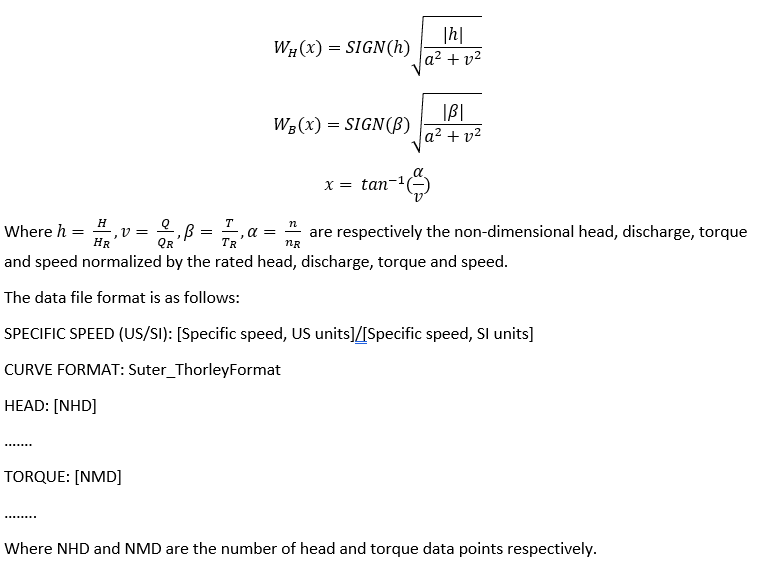
An example of Suter Thorley format curve is given in the figure below:

Suter Chaudhry Format
One other file format uses a method attributed to Suter and Chaudhry, described in Applied Hydraulic Transients (M. Hanif Chaudhry, 1979). In this format, pump characteristic data is presented in term of 2 angular functions, pump head WH(x) and torque WB(x) which are determined using the following relations:
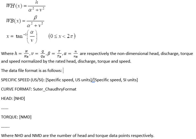
An example of Suter Chaudhry format curve is given in the figure below:

Turbines
The turbine data format is similar to that used for circular format for pumps, except data is also required for different wicket gate positions. Suter format is not currently supported for turbines. In addition, turbines in WaterGEMS are always expected to operate in the first quadrant of operation (positive flow and positive speed).
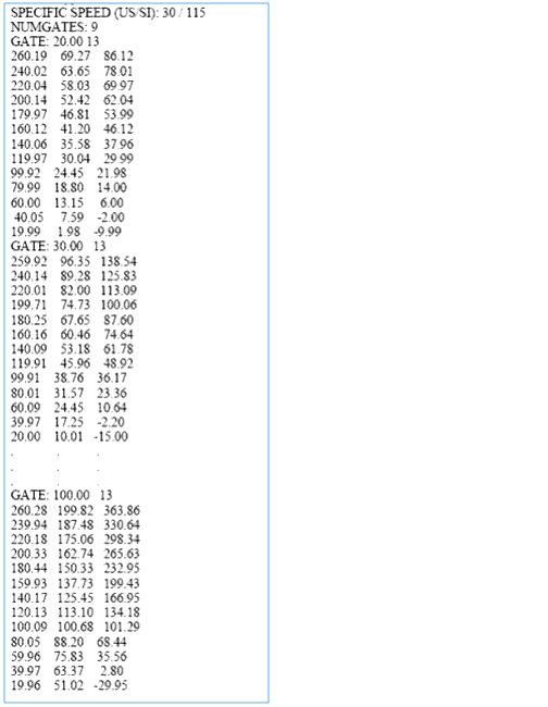
The data file format is follows: SPECIFIC SPEED (US/SI): [Specific speed, US units] / [Specific speed, SI units]NUMGATES: NGGATE: WG1 ND1H1,1 Q1,1 P1,1H1,2 Q1,2 P1,2. . .. . .H1,ND1 Q1,ND1 P1,ND1. . .. . .GATE: WGNG NDNGHNG,1 QNG,1 PNG,1HNG,2 QNG,2 PNG,2. . .. . .HNG,NDNG QNG,NDNG PNG,NDNG
Where NG represents the number of different wicket gate openings described in the data; WGi represents a particular gate opening value; ND is the number of data points for the associated gate opening value; H, Q and P represent head, flow and power respectively (the first subscript of H, Q and P denotes wicket gate position index, while the second one is the data index for that wicket gate position);
It should be noted that:
(a) WGi, Hi,j , Qi,j and Pi,j are in percent (%) relative to rated head, flow and power (H, Q and P), or full gate opening (WG)
(b) WGi increases with i.
(c) Hi,j , Qi,j and Pi,j decrease with j, for fixed i.
(d) WGi should be between 20% and 100% (inclusive). Below 20% gate opening, WaterGEMS currently assumes a linear decrease in flow until the time the gate opening equals 0%.
An example of turbine characteristics is given in the figue below (note: some data is omitted so the figure can fit on a single page).
Entering user-defined pump and turbine characteristics
To enter user-defined pump and turbine characteristics, users should follow these steps:
- Close down WaterGEMS .
- Browse to C:\Program Files\Bentley\<Product Name>10 and open the QuadrantCurves.txt file.
- Enter the data using one of the formats described above. Pump data should go immediately after the [PUMP] line in the QuadrantCurves.txt file; turbine data should go after the [TURBINE] line.
- Make a note of the specific speed values entered for the pump / turbine.
- Save and close QuadrantCurves.txt.
- Open WaterGEMS , and then open a file (or create a new one).
- For a pump, go to Components > Pump Definitions > Transient > Specific Speed and select the specific speed for the data you just entered (see step 4). Now for each pump that uses this pump definition, WaterGEMS will use the user-defined pump characteristics in the calculations.
- For a turbine, right-click on the turbine and select Properties. Then chose the appropriate specific speed in the 'Specific Speed' field (see step 4). WaterGEMS will now use the user-defined turbine characteristics in the calculations.